Core to the construction of a
pipeline is
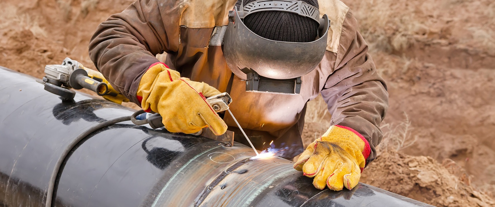
girth welding of
line pipes i.e. faster the welding rate, more is the progress achieved.
Girth welding (Ref 1) process is involved in mainline welding, tie-in welding and repair welding of the
line pipes. Pipeline girth welding, however, poses a lot of additional challenges when compared to the usual plant welding or mill welding of pipes, as it has to be performed under the surveillance of Mother Nature.
The growth of
pipeline industry necessitated the utilization of higher strength steel and larger sizes of
line pipes for the overall economic viability of various projects. Various developments and advancements achieved in the girth welding processes of the
line pipes have allowed the Pipeliners to dream of longer and larger
pipelines with high tensile strength steel.
Note: This article is focused strictly on girth welding process for the construction of pipelines. The target readers are the professionals who are involved in the pipeline welding processes but are not the experts as this article covers the hydrocarbon pipeline welding in a bird's eye view perspective and does not dig into the minutest details.
Deposition Rate: Rate that weld metal can be deposited by a given electrode or welding wire, typically expressed in 'lbs/hr' or 'kg/hr'. It is based on continuous production, not allowing time for stops/ starts/ cleaning or inserting new electrodes. Deposition Rate is directly proportional to the welding current being used.
- On a Constant Current Machine – increasing the amperage increases the deposition rate
- For a Constant Voltage Machine – increasing the wire feed speed increases the deposition rate
Deposition efficiency: Relationship of the weight of weld metal deposited versus the electrode consumed in making the weld. Mostly defined as a percentage e.g. 100 kg of coated electrodes with an efficiency of 65% result in 65 kg of weld metal deposited.
Uphill Welding: If the direction of travel of the electrode is against gravity then the welding technique is called uphill welding. Uphill progression is typically considered to make a stronger more robust joint, but has higher potential for burn through.
Downhill Welding: If the direction of travel of the electrode is towards gravity then the technique is called downhill welding. Downhill welding process is very sensitive to welding parameters and requires a tighter control as a slight variance may result in slag inclusions and lack of penetration defects.
Being the backbone of the pipeline construction, selection of welding process should consider the following:
-
Material of the line pipe: With the development of high-grade steel, modern pipeline industry is using line pipes of minimum yield strength greater than 56,000 psi (i.e. Gr. X56) which mostly consists of micro-alloyed (Ref. 2) steel. As the strength of line pipes is increased by micro-alloying, the susceptibility of hydrogen induced cracking (HIC) of the line pipes in the heat affected zone (HAZ) also increases. Although, line pipes up to material Gr. X65 has been successfully welded by SMAW process using cellulosic electrodes (Ref. 3) with/ without pre-heating, however, for welding of pipes of material grade X70, pre-heating of the pipe ends before welding up to a temperature of 120oC to 140oC (250oF to 290oF) is a must to prevent HIC, while cellulosic electrodes can be used for girth welding.
It is recommended to use low hydrogen (H2) welding processes or GMAW for welding X80 grade or higher grade material pipes. However, SMAW process with basic electrodes (low/ very low hydrogen electrodes) may be used for welding X80 grade material pipes with due deliberations only.
-
Diameter & wall thicknesses: Execution of large diameter pipeline and/ or thick-walled line pipes requires higher weld volume, or in other words, the faster deposition rate of the weld metal. This can be achieved by automation of the girth welding process. All welding process deployed in pipeline construction, except SMAW welding process, are amenable to automation. Semi-automatic, mechanized and automatic modes of welding process or their combination shall be utilized for long distance pipelines for increasing productivity and timely completion of the project. Automatic welding can be applied on pipes with wall thickness ≥ 13.0 mm with diameter ≥ 24” (610 mm) for increasing weld productivity.
| Pipe Size (NPS) |
Number of Welds per Day per Welding crew |
| Automatic Welding |
Semi-automatic/ manual Welding |
| 323.8 mm (12.75”) |
-- |
60 a |
| 457.0 mm (18”) |
-- |
50 a |
| 610.0 mm (24”) |
60 |
40 b |
| 910.0 mm (36”) |
45 |
26 b |
| 1219.0 mm (48”) |
35 |
20 b |
| 1422.0 mm (56”) |
20 |
8 b |
Notes:
- All passes by manual welding.
- Root pass and hot pass are performed by manual welding process and remaining passes by semi-automatic process.
|
-
Location of welding: The girth welding of the pipeline is performed in situ at the location through which the pipeline is traversing i.e. desert, tropical rain forest, permafrost area, or on a lay barge in case of submarine pipelines. Therefore, the ambient temperature, humidity etc. shall also be considered before selection of welding process. For performing welding of the pipes in freezing or near freezing temperatures require preheating of the pipes to minimum 16oC to prevent any thermal shock in the HAZ. If the location lies in tropical rain forests or high humidity location such as lay barge working near Indian or African coasts, utilization of low hydrogen electrodes results in porosity. Under such condition normal cellulosic electrode, which needs moisture for arc stabilization, gives sound weld than low hydrogen electrode. In case other requirement does not give the privilege of avoiding low hydrogen electrode, the electrodes must be baked to reduce their moisture content before welding.
Sometimes, pipelines are to be laid in existing trench wherein clearance around the pipe is not sufficient for traveling by the automatic welding machine all around the line pipes. In such condition, the manual or semi-automatic process may be used.
-
Construction period/ productivity: Pipelines construction generally suffers from the huge crunch of time. Tight construction schedule demands to lay the pipeline at a faster rate, which demands higher productivity with minimum repair rate. In offshore, construction duration becomes directly proportional to the project CAPEX, as the charges of barge deployed for construction are based on day rates. The progress of construction in pipelines is therefore mostly monitored by a number of joints (welds) per day. Mainline welding has been therefore developed as a mass production process. Factory beveled pipe ends to support downhill welding process for faster welding is a norm in the pipeline.
Most of the lay barges utilize fully automatic welding process (GMAW) for welding the line pipes for achieving faster weld rates and minimum repairs. Precaution must be taken in the selection of pipe end bevel for pipes proposed to be welded by automatic welding, as different automatic welding machines require different kinds for pipe end bevels for proper fusion. Due to this, beveling of the pipes is sometimes carried out on the barge. Repair rate may shoot up if trained operators are not deployed to operate the automatic welding machines.
SMAW process has the least productivity and SAW process has the maximum weld metal deposition rate. In pipelay mega-barges, where pipes are fed into the firing line after double/ triple or quadruple jointing, submerged arc welding is deployed for joining the section of pipes before feeding into the firing line for saving time.
-
Weldment properties: The girth welds on the pipeline section may fall under the highway/ railway crossing or risers or a submarine free span which are subjected to cyclic loading. Also, laying stresses in the pipeline during installation may result in straining of the weld (reel laying). In case of service fluid being corrosive, the weld metal also has to also resist such degradation.
Girth weld in hydrocarbon pipelines has to meet all requirements in terms of minimum tensile strength, fatigue strength, fracture arrest properties, corrosion resistance, hardness, ductility etc. equal to or higher than the base metal of pipe. Procedure qualification of the girth welding shall include testing for these properties of the weld & heat affected region of the pipe ends. Therefore, selection of welding process, electrode, and other welding parameters shall consider these requirements beforehand.
-
Quality (in terms of soundness & repair rate): High-quality welds which guarantees reliability and low repair rates are critical for pipeline construction. Poor quality of welds not only hinders project progress but reduces the reliability of the overall pipeline system. Many times, pipelines are laid in the remotest locations. Pipeline girth welding should meet the highest quality parameters, as once the pipeline is laid and installation spread is demobilized from that location, it becomes very difficult to approach the location for any repairs in future.
If a pipeline gets damaged, not only significant revenue is lost and damage is caused to the environment, but also the leakage causes a potential danger to the local population. A small incident of failure can shake the confidence of the locals. This will make execution of the future projects much difficult. The high reliability of the pipelines as compared with other modes of transportation is the USP for this initially high CAPEX infrastructure. Therefore, welding process shall be selected such that girth welds (Ref 1) are of high quality to ensure more reliable pipeline systems.
-
HSE (Health, Safety & Environment): Welding process, whatever advanced, results in a lot of different types of health, safety, and environmental concerns. The fumes and gas emitted during welding process contain nitrous oxides (NOx), carbon dioxides/ monoxides, ozone (O3), shielding gases such as argon (Ar), helium (He) etc. and very fine particles which are not only detrimental to the health of welders but also to the environment. Lack of breathable air in confined spaces is one of the commonest reasons for accidents. Exhaust fans shall be deployed to prevent accumulation of harmful fumes in the welding enclosures. Also, due to hot working involved in the welding process, immense care should be taken to avoid any blast or fire due to the vicinity to the inflammable material, particularly, if welding operation is being performed near existing hydrocarbon installations. In case of welding hook-ups with the existing lines, the existing lines shall be properly cleaned & flushed to make it hydrocarbon free before the commencement of welding. If welding procedure is using high voltage/current source then the electrical wires shall be new and fit for purpose with no jointing or minimum joints. In case, gas cylinders are utilized then the standard operating procedure (SOP) shall take care of proper keeping and handling of such cylinders to prevent an accident due to any act of negligence.
-
Cost: Welding economics plays the most important role in the selection of process and welding process specification for girth welding. Same weld can have different costs depending upon the selection of:
- Deposition Rate
- Deposition Efficiency
- Welding Process (SMAW, GMAW, FCAW, SAW)
- Joint Design
- Welding Volume
- Arc Time Factor
Welding cost for a joint can be estimated by following formula:
| Total weld cost |
= |
Total arc time cost |
+ |
Non-arc time cost |
+ |
Cost of filler metal
|
|
= |
Total Arc Time can be calculate by:
- Determining weld metal volume need to be deposited
- Determining deposition rate for given process
- Calculating total time needed to make weld
|
+ |
Factors effecting Non-arc time:
- Interpass cleaning
- Electrode change out
- Welder position change
- Weld joint preparation
- Fitting/ tacking
|
+ |
Weld volume required depending upon:
- Joint Design × Deposition efficiency
|
-
Direction of weld travel (Downhill and Uphill): Direction of weld travel is one of the essential variables in pipeline welding. As the construction duration is primarily dependent upon welding speed, mainline welding is carried out by downhill progression and welding station piping or tie-in welding is performed by uphill progression. Line pipes ends for mainline welding are plant machined and fit-up for welding is achieved by deploying internal hydraulic clamps; whereas the ends of pipes to be utilized for terminals/ stations piping are prepared manually at site and external clamps along with tack welds are applied for fit-up of pipes.