HDD Design Analyser User Manual

HDD Analyser is a comprehensive program for the design analysis of pipelines crossings by horizontal direction drilling methodology. HDD Analyser performs the pipeline stress analysis and HDD design calculation in compliance with the International Codes and Standards. This program can be used to analyze and assess the safety of a given HDD crossing for pipelines during installation, post-installation hydrotest and during operation stages.

HDD Analyser performs the following calculation:

  1. Drill Path Analysis based on geometric considerations.
  2. Pipe pulling load calculation as per “Engineering Design Guide”, published by PRCI.
  3. Stress Analysis of the pipeline in compliance with the latest editions of ASME B31 codes
  4. Minimum Elastic Bend Radius (MEBR) calculation based on stress analysis result.
  5. Maximum permissible overburden of pipe w.r.t pipe collapse strength.
  6. Maximum distance between rollers for supporting the pipe string.


HDD Analyser performs the design calculation for the typical HDD drill path (banana shaped) considering it as a series of straight lines and curves as shown below:

HDD Crossing
Fig. Typical Horizontal Directional Drilling Crossing

User is required to provide the input for the integrated drill profile (indicated in green color in the above picture). HDD Analyser utilizes the user input integrated drill profile to generate the segment-wise length of the individual sections suitable for applying loads. User is required to provide following inputs:

  • Total horizontal length of the crossing (Lhorizontal)
  • Maximum depth of the crossing (Depth)
  • Entry angle (θin) and exit angle (θout) of the pipeline
  • Radius of curvature for the pipe side (Rin) and rig side (Rout)
  • Entry height w.r.t reference level (Rin) and exit height w.r.t to reference level (Rout)

Based upon the User’s input, HDD Analyser calculates the segment-wise lengths geometrically i.e. straight lengths along the slopes i.e. (AB downwards and EF upwards), curved lengths (i.e. BC downwards and DE upwards) and straight length along the horizon (i.e. CD).

In case, User wants to perform the calculation for a shallow HDD profile i.e. with no straight length along the horizon (i.e. CD = 0), then the same can be performed by entering the accurate horizontal length of the crossing for shallow HDD. If the calculated length of CD by HDD Analyser is negligible w.r.t. total length of crossing then it itself equates it to zero and performs the segmentation accordingly.


The pulling force calculation is based on elementary finite difference calculation of the pull force required to install the individual pipeline segments from entry point to exit point of the pipeline in the reamed hole. The total pull force required to install the pipe is determined by summing the individual forces required to pull the pipe through each of the straight and curved sections defined in the “drilling hole profile” above.

The required pull force for pulling the pipe string is calculated as the force required to overcome combined effects of the following:

  • Frictional force
  • Drag force
  • Force due to change in elevation (potential) of pipe section
The pull force required to pull the pipe through each of the straight and curved sections is calculated as per the following formula:

Straight Section HDD Crossing
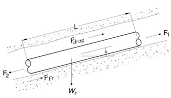
Fig. Free body diagram for pulling of straight pipe section

For any straight section, the pulling force (F2) is calculated from static force balance as follows:

F2 = F1 + | FFr | + Fdrag ± FP


Curved Section HDD Crossing
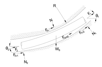
Fig. Free body diagram for pulling of curved pipe section


For any curved section, the pulling force (F2) is calculated from static force balance as follows:

F2 = F1 + 2 | FFr | + Fdrag ± FP

Where,
 F1 =  Force resisting the movement of the remaining pipe at Point 1
(Summation of forces required to pull the pipe on the left side)
 FFr =  Frictional force between the pipe and the soil/ rollers
 Fdrag =  Drag force of bentonite acting on pipe
 FP =  Force due to change in elevation (potential) of pipe section
(It is negative when the pipe is pulled down the drilled hole and positive when the pipe is pulled up the drilled hole)
Frictional force shall be overcome by the pulling force applied by the rig in order to pull the pipe inside the drilled hole. Frictional force acting on the pipe string is classified as following:

  • the frictional force acting between rollers and pipe
  • the frictional force acting between soil and pipe down hole

Frictional force acting between rollers and the pipe
Before the start of pulling operation of pipe, the pipe string is prepared and tested on roller supports kept at regular interval. During the pulling of pipe, the rig has to apply pull force to overcome the frictional force acting between the rollers and the pipe. Maximum frictional force between rollers and the pipe is acting at the start of pulling operation as the complete section of the pipe is kept on rollers and gradually decreases to zero near the end of pulling operation when the complete pipeline string leaves the roller and enters downhole. This frictional force is calculated as per the following formula:

FFr, R  =  We ∙ μroller ∙ Lr

Where,
 FFr, R =   Frictional force acting between rollers and the pipe
 We =   Weight of empty pipe on rollers
 μroller =   Co-efficient of friction between pipe and roller support
 Lr =   Length of pipe string remaining on roller supports


Frictional force acting between soil and pipe
The methodology for calculation of frictional force acting between pipe string (down-hole) and the soil depends upon the shaped of the segment i.e. the segment is straight or curved.

Straight Section
The frictional force acting between soil and pipe string downhole in a straight section is given by the following equation:

FFr, soil  =  Ws ∙ L ∙ μsoil ∙ cos θ

Where,
 FFr, soil =   Frictional force acting between soil and the pipe string downhole
 Ws =   Weight of submerged pipe downhole
 μsoil =   Co-efficient of friction between pipe and soil
 θ =   Angle between pipe direction downhole and the horizon

Curved Section
The frictional force acting between soil and pipe string downhole in the curved section is given by the following equation:

FFr, soil  =  μsoil ∙ N

Where,
 N =  Average normal contact force in the curved section
The drag force is generated due to fluidic drag between pipe and viscous drilling fluid i.e. bentonite mud. It is directly proportional to the external surface area of the pipe and co-efficient of drag between the pipe and bentonite mud. The drag force (Fdrag) is calculated as per the following equation:

Fdrag   =   π ∙ D ∙ L ∙ μmud

Where,
 D =   Outside diameter of pipe
 L =   Length of pipe in the downhole
 μmud =   Drag co-efficient between pipe & bentonite mud
The change in elevation of the pipe section either supports the pulling operation or obstruct the pipe movement depending upon the pipe is pulled down the drilled hole or up the drill hole. It also depends upon that the submerged weight of pipe is acting downwards or is buoyant upwards. In case, the drilled hole section is horizontal, then there will be no change in elevation and this force will be zero.

The force due to change in elevation (potential) of pipe section ( FP ) is calculated as per following equation:

FP  =  Ws ∙ L ∙ sin θ

Where,
 Ws =   Submerged weight of pipe downhole
 L =   Length of pipe in the downhole
 θ =   Angle between pipe direction downhole and the horizon


Pipeline is checked against allowable longitudinal stresses and allowable combined stresses as per ASME B31.4/ ASME B31.8 for the following load cases:

  • Installation Case
  • Post-installation Hydrotest Case
  • Operation Case
During installation pipe string does not have any internal pressure (or any resultant hoop’s stress), therefore, only longitudinal stresses are calculated for the installation case. For post-installation hydrotest and operation case both longitudinal stresses as well as combined stresses are calculated considering restrained pipe.
For locations in the drilled path profile that is suspected of being a critical stress location, longitudinal stress ( SL ) shall meet the following criteria as per ASME B31.4/ ASME B31.8:

| SL |  ≤  FL × SMYS

Where,
 FL =   Allowable percentage of SMYS for longitudinal stress
 SMYS =   Specified Minimum Yield Strength of pipe material

Also, net Longitudinal Stress in restrained pipe is equal to:

SL   =  SP + ST + SX ± SB

Where,
 SP =  Longitudinal stress due to internal pressure
 ST =  Longitudinal stress due to thermal expansion
 SX =  Longitudinal stress due to axial loading
 SB =  Bending Stress (due to drill profile curvature radius and overbend on the rollers) either tensile (+) or compressive (-), whichever leads in higher value of ‘SL

Longitudinal Stress due to Internal Pressure
The longitudinal stress due to internal pressure ( SP ) in restrained pipelines is equal to:

SP  =   ν × SH

Where,
 ν =  Poisson's ratio of steel of pipe
 SH =  Hoop's stress due to internal pressure of pipe
=  Pd ∙ Ds / ( 2 ∙ ts )
 Pd =  Internal pressure of pipe (i.e. equal to design pressure for operation case and equal to hydrotest pressure for hydrotest case)
 Ds =  Outside diameter of pipe
 ts =  Wall thickness of pipe

Longitudinal Stress due to Thermal Expansion
The longitudinal stress due to thermal expansion ( ST ) in restrained pipelines is equal to:

ST  =   Es ∙ α ∙ ( Tamb − Td )

Where,
 Es =  Modulus of Elasticity of steel
 Tamb =  Ambient temperature of pipeline during installation
 Td =  Design temperature of pipeline (buried)
 α =  Linear coefficient of thermal expansion of steel

Longitudinal Stress due to Axial Loading
Longitudinal stress due to axial loading ( SX ) other than thermal expansion i.e. pulling force is calculated as per the following equation:

SX  =   R / A

Where,
 R =  Pull force at the specified location
 A =  Cross-sectional area of steel

Bending stress due to route curvature
Bending stress ( SB ) due to route curvature is calculated as per following equation:

SB  =   Es ∙ Ds / ( 2 ∙ R )

Where,
 Es =  Elastic modulus of steel of pipe
 Ds =  Outside diameter of pipe
 R =  Radius of curvature of drill path
For locations in the drilled path profile that is suspected of being a critical stress location, Combined Stress ( SA ) shall meet the following criteria as per ASME B31.4/ ASME B31.8:

| SA |  ≤  FA × SMYS

Where,
 SMYS =  Specified minimum yield strength of pipe
 FA =  Allowable percentage of SMYS for combined stress
( FH or FO depending upon combined stress is being calculated for hydrotest or operating condition)

The combined bi-axial stress state of the pipeline in operating and hydrotest mode is calculated using following equation:

SA  =  [ SH 2 − SH ∙ SL + SL 2 ]1/ 2

Where,
 SH =  Hoop's stress due to internal pressure
 SL =  Longitudinal stress


Minimum (allowable) Elastic Bend Radius (MEBR) for the pipeline profile across the crossing location is determined from the allowable longitudinal stress for following cases:

Minimum (allowable) Elastic Bend Radius (MEBR) for the pipeline profile across the crossing location is determined from the allowable combined stress for following cases:

The minimum (allowable) radius of curvature for the pipeline at the crossing location shall be the product of highest value of the minimum pipeline elastic bends radii as computed from the considerations outlined as above and the multiplication factor to compensate for drilling inaccuracies.


The pipe string is checked for maximum permissible overburden on pipe to check that the empty pipeline is safe from collapse at any point due to caving of the drilled hole. The external pressure on pipe due to collapse of drilled hole is calculated as below:

Pe   =  ( Hsoil ∙ ρsoil + Hwtr ∙ ρwtr )

Where,
 Pe =  External pressure on pipe
 Hsoil /Hwtr =  Height of soil/ water column above pipe
 ρsoilwtr =  Density of soil/ water column above pipe

The critical elastic buckling pressure of a theoretically perfect pipe (perfectly round with a constant thickness) due to hydrostatic pressure loading only is given by the following expression:


Pe  =   2 Es  t  ( t  ) 2 
             
1 - υ2  Ds  Ds − t 

Where,
 Pc =  Elastic buckling pressure of pipe
 Es =  Elastic modulus of steel of pipe
 Ds =  Diameter of pipe
 t =  Corroded wall thickness of pipe
=  ts − CA
 ts =  Wall thickness of pipe
 CA =  Corrosion allowance