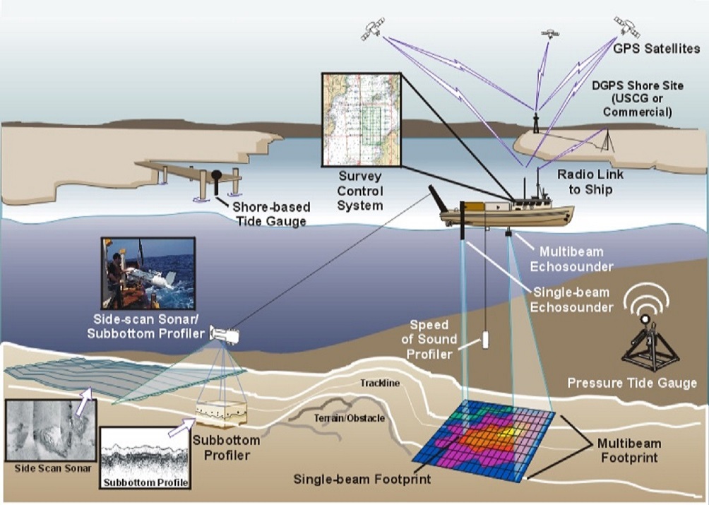
Survey for Offshore Pipelines Subsea Pipeline


Offshore pipeline route survey is among one of the few first (pre-engineering) and last (as-built) steps which are required to be carried out in case you want an offshore pipeline to be brought into reality. Once an offshore pipeline project is conceptualized by a desktop study of the preliminary routing of the pipeline based on data in public domain (such as GEBCO, NOAA) or field data available with the Operator, the next wise step is to go for a reconnaissance (recce) survey of the route. Survey of the pipeline route not only provides eyes to the Designer but also to the Constructor, as all the stake holders are visionless underwater.

The data gathered from an offshore survey campaign can be classified broadly into two categories:

  1. Geophysical i.e. the data gathered without any seabed intervention
  2. Geotechnical i.e. the data gathered by some type of seabed intervention

Survey offshore pipeline
Some may say that metocean data can also be considered part of offshore survey, but the equipment and methodology of metocean data collection is a lot different than what I am going to discuss in this article, hence I am excluding it from the scope of this article.


There are four different stages of pipeline development where survey is primarily carried out along the offshore pipeline route:

The first field survey is called Reconnaissance or recce survey which is carried out during the concept stage of the pipeline. Once the pipeline route is planned based on desktop study, it’s important to survey the area to obtain data for further studies. Now, as the probability of encountering obstacles such as shipwrecks, seamounts, pockmarks, corals etc. is high and the terrain is unknown, generally a wider corridor, varying from 500 m to 5000 m (depending upon length and location of the pipeline) is chosen. The focus during a recce survey should be to cover the width rather than the precision of data. Wider survey corridor will support in re-routing the pipeline in case of identification of any detrimental seabed feature or geohazard, which was not known during desktop study. The geotechnical investigations during recce are kept at a minimum, and are carried out typically to characterize the soil, since the pipeline route is uncertain, and re-routing of pipeline will mean emptying the pockets again. Recce survey data is utilized as input for basic engineering or front-end engineering design (FEED) activities.

In case, the development is planned within the offshore brownfield then recce survey is generally avoided, as such data is expected to be available with the Operator.

Pre-engineering route survey is the most detailed survey amongst all others. Mostly, it is planned in such a way that the data gathered from pre-engineering survey is available before detail engineering of the pipeline. The scope for pre-engineering survey is to provide sufficient data for detail design and sometimes, for pipelay/ construction related activities also. Its scope should also include the detail investigation of critical areas which have been identified based on data and basic engineering/ FEED of the pipeline, such as crossings over existing installation (pipelines/ cables), corals, calcarenite zones etc. The corridor width mostly varying from 200 m1000 m (i.e. 100 m500 m on either side of the route) depending on pipeline length and confidence of the designer on the route.

Also, detailed geotechnical investigations for collection of soil data for pipe-soil interaction study, crossing support design, trenching locations etc. are performed during this campaign. Generally, the vessels for and geotechnical survey are different.

Pre-construction survey of the pipeline route is performed just before the installation of the pipeline to capture any changes or asset developments or hazards which might have taken place between the pre-engineering survey and installation period. The seabed in coastal areas are generally dynamic and movement of sand/ clay due to change in current flow pattern or trenching/ dredging in the nearby location may result in change in bathymetry which may result in installation issues. Also, certain hazards/ areas are identified during engineering which may require further investigation before going to the field; in those cases also pre-construction survey comes in handy. Pre-construction survey also serves as anchor clearance survey and hence the width of geophysical corridor shall be sufficient for determining the anchor pattern for the pipelay barge (generally 500 m2000 m on the either side of the route). As a norm, pre-engineering survey is carried out by the Operator and pre-construction survey comes under the scope of the Installation Contractor. Geotech investigations are kept at a minimum during pre-construction survey, except for trenching locations or other seabed intervention, as change in sub-bottom layers is unlikely.


Post construction surveys (geophysical only) can be categorized in two categories:
  • As-laid Survey: This is done by continuous touch-down point monitoring during the pipe laying or by a separate survey. In case continuous touch-down monitoring is used, pipeline position is confirmed after completion of pipeline installation. Continuous touch down monitoring may not identify possible horizontal curve pull-out, and therefore positioning of pipeline to be confirmed after completion of installation activities. The as-laid survey should include the following:
    • position and depth of the pipeline, including location of in-line assemblies, anchoring and protective structures, tie-ins, supports etc.
    • identification and quantification of any free spans with length and gap height
    • determination of position of start-up and lay down heads
    • video documentation of the submarine pipeline system
  • As-built Survey: The as-built survey is performed after all works on the submarine pipeline system, including crossings, trenching, gravel dumping, artificial back-fill, tie-in, riser installation, etc., are completed. The as-built survey of the installed and completed pipeline system is performed to verify that the completed installation work meets the specified requirements, and to document any deviations from the original design. The as-built survey shall include the corrosion protection system where potential damage to the coating and sacrificial anodes is required to be documented. The as-built survey should include the following in addition to the requirements for as-laid survey:
    • Out-of-straightness measurements, as applicable
    • depth of cover or trench depth
    • location of areas of damage to pipeline, coating, and anodes
    • location of any areas with observed scour or erosion along pipeline and adjacent seabed
    • verification that the condition of weight coating (or anchoring systems that provide for on-bottom stability) is in accordance with the specification
    • description of wreckage, debris or other objects which may affect the cathodic protection system or otherwise impair the pipeline
    • video documentation of the submarine pipeline system

Apart from the above surveys, free span rectification survey, pre-trenching survey, post-trenching survey, Grout bag/ concrete mattress sleeper post-installation survey may also be conducted depending upon the design and contractual requirements of the pipeline projects.


Geophysical investigation for offshore pipeline route is carried out with the following objectives:
  • To establish accurate bathymetry and seabed morphology for the survey corridor.
  • To obtain continuous seabed & sub-seabed profiles along the survey corridor.
  • To identify any obstruction along the pipeline routes such as shipwrecks, debris etc. which can be detrimental in pipeline installation and operation.
  • To carry out manual survey in the intertidal zone, shoreline mapping and beach profiling up to Land Fall Point (LFP) using the spring tide advantage.
  • Geo-hazard identification (potential Shallow Gas, pockmarks, unstable slopes, significant depressions, seamounts etc.).
  • Preparation of route alignment drawings.
  • To connect existing local plant grid with offshore survey datum.
  • Identify environmentally sensitive habitats, corals etc.

Survey offshore pipeline


The parameters used to transfer the ellipsoidal surface of earth to a flat surface of paper are known as geodetic parameters. During the geophysical survey geodetic parameters are utilized to translate the raw survey data related to positioning of the vessel to a workable chart.


Survey offshore pipeline


Following two types of controls are maintained for accurately locating/ positioning during a survey campaign:

Horizontal Control: Horizontal control is required for accurately connecting any point on the surface of earth with a point on the survey chart. For achieving this, various geodetic systems which divide the surface earth into various zones have evolved amongst which World Geodetic System (WGS) has become a standard for use in cartography, geodesy, and navigation. It comprises of a standard coordinate system for the Earth, a standard spheroidal reference surface (the datum or reference ellipsoid) for raw altitude data, and a gravitational equipotential surface (the geoid) that defines the nominal sea level.

The latest revision is WGS 84 (a.k.a. WGS 1984, EPSG: 4326), established in 1984 and last revised in 2004.

The coordinate origin of WGS 84 is meant to be located at the Earth's center of mass; the error is believed to be less than 2 cm. The WGS 84 datum surface is an oblate spheroid (ellipsoid) with major (equatorial) radius a = 6378137 m at the equator and flattening f = 1/298.257223563. The polar semi-minor axis b then equals a times (1 − f ), or 6356752.3142 m.

Currently, WGS 84 uses the EGM96 (Earth Gravitational Model 1996) geoid, revised in 2004. This geoid defines the nominal sea level surface by means of a spherical harmonics series of degree 360 (which provides about 100 km latitudinal resolution near the Equator). The deviations of the EGM96 geoid from the WGS 84 reference ellipsoid range from about −105 m to about +85 m. EGM96 differs from the original WGS 84 geoid, referred to as EGM84.

However, many operators utilize local geodetic datum is more accurate for locating within their field, for example ONGC utilizes Everest 1830 datum, ADNOC offshore utilizes Clark 1880 (modified) geodetic datum on the Nahrwan 1967 Ellipsoid, Saudi Aramco utilizes Ain Al Abd datum etc.

Vertical Control: Vertical Control is established to tie the soundings acquired during ocean surveys to known references to obtain depths. Soundings are reduced with reference to either Chart Datum (CD) or to the Lowest Astronomical Tide (LAT). Reduction of soundings to the Mean Sea Level (MSL) is seldom done.

Mostly, all offshore surveys are required to be reduced to the required datum (CD or LAT) using real-time, observed tides. Also, see functioning of tide gauge detailed below.


Survey offshore pipeline
Knowing ones precise position out at sea and over water at every given instant is fundamental to the process of any Surveying as all other data are correlated with respect to this position to develop the over-all picture in terms of drawings, charts and maps. The more accurately one knows the position out in the survey field, more accurate is the final rendition of data. Positioning system provides the easting and northing (X, Y) coordinates of any location.

Global Positioning System (GPS): The Global Positioning System (GPS) is the state-of-the-art technology in Navigation and Positioning. The GPS, originally, NAVSTAR (Navigation Satellite timing and Ranging) GPS is a satellite-based navigation, timing, and positioning system. GPS receiver calculates its position by precisely timing the signals received from the GPS satellites orbiting high above the Earth at orbital heights of 20,000 to 24,000 km. Each satellite continually transmits messages containing the time the message was sent, orbital information (the ephemeris), and the general system health and coarse orbital data of all GPS satellites. The receiver measures the transit time of each message and computes the distance from each satellite. A position thus obtained is called a GPS or Autonomous GPS position and is accurate to ± 7 meters to ± 12 meters due to various factors contributing to the errors in determining the precise distance between the Satellites and the receivers. This is excellent standards for normal vessel navigation but not quite adequate for precise work such as charting and mapping.

Differential Global Positioning System (DGPS): Differential Global Positioning System (DGPS) is an enhancement to Global Positioning System that uses a network of fixed, ground-based reference stations to broadcast the difference between the positions indicated by the satellite systems and the known fixed position of the reference GPS receiver. These stations broadcast the difference between the measured satellite pseudo ranges and the theoretical pseudo ranges (internally computed using the knowledge of the position of the receiver with which it has been initialized and the position of individual satellites based on the almanac and ephemerides). Once received by mobile DGPS receiver stations they correct their pseudo ranges to individual satellites by the same amount as transmitted from reference station beacon there by enabling more accurate computation of the receiver position accurate to ± 1 meter to ± 3 meters. The DGPS antenna is installed on a high point of the vessel (generally the monkey deck or the mast), where there is no or minimal obstruction between the satellites and the Antenna.
Echo sounder is a system used for determining the distance between the survey vessel and seabed at any given instance. This data forms the basis for calculating seabed depth (Z co-ordinate) at any given location. Knowledge of the depth at which the seabed is at each position with reference to a vertical datum like the chart datum is of paramount importance in developing the seabed topographic picture. Echo-sounder is based on the principle that water is an excellent medium for the transmission of sound waves and that a sound pulse will bounce-off a reflecting layer like the seabed, returning to its source as an echo. The beam transmitted is a pencil cone shaped beam hence has the limitation of illuminating acoustically only some area of the seabed that fall in the footprint of the echo sounder.

Survey offshore pipeline

The time interval between the initiation of a sound pulse and echo returned from the bottom can be used to determine the depth of the bottom using half of the two way travel time measured and using standard sound velocity in sea water which can range from 1480 m/s to 1560 m/s.

An echo-sounding system consists of a transmitter, transducer that converts electrical energy to sound and vice versa, a receiver that picks up the reflected echo and processes it, electronic timing and amplification equipment, and an indicator display which could be a paper hard copy type, digital type or both.

  • Single Beam echo sounder (SBES) or Multi-beam echo sounder (MBES)
  • Mounted on the side of the vessel or hull mounted

Survey offshore pipeline
Side-scan sonar is used to produce a morphological map of the area and create efficiently an image of large areas of the sea floor. The aim of conducting side scan sonar sweep is to obtain seabed information along the route e.g. anchor scours, large boulders, debris, bottom sediment changes, pockmarks and any item on the seabed having a horizontal dimension more than 0.5 m. General requirements for resolution of sonar imagery is to detect objects on the seabed within ±0.5 m along-track and ±1.0 m across-track.

Side scan sonar uses a sonar device that emits a fan-shaped pulse down toward the seafloor across a wide angle perpendicular to the path of the sensor through the water, which may be towed from a surface vessel or submarine, or mounted on the ship's hull. The intensity of the acoustic reflections from the seafloor of this fan-shaped beam is recorded in a series of cross-track slices. When stitched together along the direction of motion, these slices form an image of the seabed within the swath (coverage width) of the beam. The sound frequencies used in side-scan sonar usually range from 100 to 500 kHz; higher frequencies yield better resolution but less range.

The Side Scan Sonar shall be operated on a suitable range setting to achieve a minimum of 110% to 133% overlap of adjacent lines. The survey line spacing shall be adjusted based on water depths in order to achieve this. The MBES line-spacing is designed as far as practically possible to achieve the required coverage on the side scan sonar (SSS), when running SSS with MBES on a single pass.
Survey offshore pipeline
Sub-bottom profiling systems are used to identify and characterize layers of sediment or rock under the seabed and investigate the sub-seabed stratigraphy and degree of homogeneity of the subsoil. The data obtained using this system provides information on these sub-floor sediment layers.

Sub-bottom profiling systems utilize the principle of seismic reflection and refraction. Seismic reflection uses a stronger sound signal than echo location and lower sound frequencies. Sub bottom profiler has two parts –

  • Sound Source i.e. the High Voltage Capacitor Banks connected to the Sparker or Squid which is towed behind the vessel and transmits the acoustic signal generated by the bursting bubble in water created by arcing of very high voltage sparks between the broom elements, hence the name Sparker.
  • Hydrophone, which is also towed separately behind the vessel and receives the reflected acoustic signal. The data from the hydrophones directly gets connected to the Geophysical data logging system.

Survey offshore pipeline

Different frequencies of the sound pulses are reflected from the different sub-bottom layers of the seabed. Hydrophones detects and receives the reflected sound signal when it reaches the surface. The time taken by the sound to return to the ship is used to find the thickness of the layers of the sub-seabed and their orientation such as level or sloping. This enables us to visualize and stratify the sub-seabed layers into various discernable isopach. Once confirmed by random ground truth samples of seabed cores, it provides a rapid means of covering the entire survey area for details seabed stratigraphy.

SBP system operates within the 3.5 - 7 kHz range with a pulse width selectable between 0.15 and 0.5ms. The system shall be capable of transmitting at repetition rates of up to 10 Hz and be capable of penetrating and providing sub-bottom strata for a depth of at least 8m to 10m below the seabed in any soil condition.


The aim of deploying a magnetometer is to detect and measure variations in the total magnetic field of the underlying seafloor. The magnetometer is used for the detection and mapping of all sizes of ferrous objects on the seabed. This includes anchors, chains, cables, pipelines, ballast stone and other scattered shipwreck debris, munitions of all sizes, aircraft, engines and any other object with magnetic expression which could be potentially hazardous to pipelines or umbilicals and for the placement of rigs & barges.

The magnetometer is a magnet sensitive device that detects all sizes of ferrous objects on the sea floor across a wide angle perpendicular to the path of the sensor through the water, which is towed as close to the seabed as possible. Based on the variation in the earth’s magnetic field the object induces to appear as an anomaly.

The magnetometer is towed from the aft of the vessel. The magnetometer is interfaced with the vessel positioning system for fix annotation, throughout the survey. The magnetometer is equipped with either an altimeter or depth meter to ensure proper tow depth.
Motion Sensor or the Attitude Sensor is used to measure linear and angular motions of the survey vessel’s, due to the waves in the sea. The angular motions are measured using the rate gyros and the linear motions are measured using the accelerometers installed in the sensor. With the help of these accelerometers, rate gyros and a complex algorithm, the sensor computes and output the heave, roll, pitch and yaw motion of the vessel. These data sets are then fed to the depth sensors (Single beam echo sounder) for compensating the depth observed by the Echo sounders. Multibeam Echo sounder data is compensated for heave, roll, pitch and yaw motion of the vessel while the single beam Echo sounder data is compensated only for heave motion of the vessel.
Pipe liner is similar to the Sub-bottom Profiler except that the projected beam’s frequency band width is much less thus giving the required resolution to detect submerged pipelines buried in the seabed and to track & trace them in order to develop the existing pipeline profile. This objective can also be achieved by a high resolution Sub-bottom Profiler also.

Pipeline profiling systems also utilizes the principle of seismic reflection and refraction. Seismic reflection uses a stronger sound signal than echo location and lower sound frequencies. The sound pulse travels down to the seafloor. Some of the sound waves reflects-off the seafloor and some of them penetrates the seafloor. The sound waves that manages to penetrate the seafloor reflects-off the hard material of the pipeline in comparison to the softer surrounding seabed enabling clear demarcation and identification of buried pipelines. The reflected sound waves travels back to the surface, is picked up by the transducers, which processes the signals to develop the complete picture with their orientation such as indicating the burial depth of the pipeline along the route w.r.t seabed including the locations where the pipelines is exposed i.e. laid on the seabed.

Pipe liner subsea unit is either a towed body or an over the side mount. It is also possible to have a hull mounted configuration also. The subsea unit is connected to top side unit using the transducer cable. The top side unit is further connected to the geophysical data logging system either using dedicated ports such as BNC or Ethernet. The position, date, time and fix number are output from the navigation PC on one of the available RS232 serial data port to the geophysical data logger. This data gets annotated on to the Pipe liner data.


It works on the principle of a magnetic compass by aligning itself with the earth’s magnetic field. The primary sensor of the device is a electronic fluxgate magnetic device that creates its magnetic field on being provided the power supply. This magnetic field then is designed to line up with earth’s magnetic field and point to the magnetic north. Internally designed compensation cater for magnetic deviation and variation to eventually point the compass to the true north.
The periodic rise and fall of sea level causes the depth to vary from time to time. This has been addressed by referring the height of rise and fall referred to a vertical datum below which the falling sea level seldom falls. This vertical datum is referred to as chart datum and all bathymetric data are referred to this chart datum. To refer observed depth to the chart datum one has to remove the height of sea level above the chart datum at the time the depth was observed. This height of the sea level is known as the height of tide. Hence in order to reduce all observed depths to chart datum one must know the height of tide at all times the bathymetric survey has been carried out. It is to collect this tidal data that one uses the tide gauge / tide pole.

The Jetty level is well established above Chart Datum. A tide pole setup on this jetty by virtue of its coincidence with the jetty level determines the zero of the tide pole with respect to the chart datum. Thereafter all water levels observed on this tide pole are reduced to the height of tide by adding or subtracting the difference between the chart datum and the zero of the tide pole depending on whether the zero of the tide pole was above or below the chart datum respectively.


It is primarily the characteristics of the upper layer of the seabed that determine the response of the pipeline resting on the seabed. For situations where the top layer comprises a soil, the determination of soil parameters for these very shallow soils may be relatively more uncertain than for deeper soils. Also, the variations of the top soil between soil testing locations and between tested locations and non-tested locations add to the uncertainty. Soil parameters used in the design may therefore need to be defined with upper bound, best estimate and lower bound limits valid within defined areas or sections of the route. The characteristic value(s) of the soil parameter(s) used in the design shall be in line with the selected design philosophy accounting for these uncertainties.


Geotechnical investigations are carried out along pipeline route to establish soil parameters for numerical modelling of the seabed such as:
  1.  Grain size
  2.  Relative density
  3.  Depth of strata
  4.  C-φ values (Cohesion and angle of shearing resistance)
  5.  Submerged soil density
  6.  Atterberg Limits
  7.  Friction co-efficient between soil & concrete coated pipe
  8.  Poisson ratio
  9.  Elastic modulus
  10.  Soil Resistivity
  11.  Thermal Conductivity
  12.  Porosity
  13.  Bulk and dry density
  14.  Undrained Shear strength (for clays)
  15.  Internal Friction angle
  16.  Consolidated tri-axial compression
  17.  Sulphate and Chloride contents

Survey offshore pipeline

It involves collecting soil samples from the seabed upto required depth (generally 3m) below undisturbed seabed level and then obtaining data during sample collection and by testing the soil samples in the laboratories.

Geotech investigation is carried out primarily during recce, exhaustively during pre-engineering and sometimes (mostly for re-verification) during pre-construction stage. Geotechnical investigations provide the data for pipe-soil interaction studies and helps in finalizing the type of equipment to be deployed in case of trenching/ dredging is required along the route.

In a layman’s term, we can say geophysical survey is like taking photos and X-rays of the seabed and geotechnical survey is like laparoscopic investigation of the seabed. So geophysical survey provides vision and geotechnical survey provides engineering numbers for design.


Survey for offshore pipeline Rock coring is considered the main line of soil investigation for pipelines. Underwater rotary rock corers are used to recover undisturbed core samples of hard soils and rock. In order to recover a high quality and undisturbed core sample, the core tube is made static. Rotary rock corers are designed as double or triple tube devices where the innermost tube acts as a core liner, the middle tube, if present, acts as a holder and the rotating outer tube carries the hollow drill bit. As the bit cuts down through the soils and rock, the core created passes into the liner in a relatively undisturbed state. Rotary drilling mechanisms can be electrically or hydraulically driven via umbilical cables to the surface. The systems is mostly supplemented with a video camera on the seabed frame to improve operational monitoring and control. The drilling fluid used to lubricate and cool the drilling process can be either water or a ‘mud’ flush.
A gravity corer consists of a steel tube with a plastic liner to retain the core sample. The penetrating end of the tube is fitted with a cutter and a concave spring-steel core-catcher to retain the sample when the corer is retracted from the soil and recovered on the vessel. A set of heavy weights, up to 750kg, is attached at the top end of the tube above which is a fin arrangement to keep the corer stable and vertical during its fall to the seabed. A deployment and recovery line is attached to the top of the corer. Normal practice is to lower the device to within 10 m of the seabed before releasing it. Gravity core tubes range in length from 1m up to 6m.

A gravity corer is normally deployed by a deck crane, with a safe working load of upto 2 tonnes (depending on size of the corer), with a free-fall winch capability. Gravity corers are appropriate for use in very soft to firm clays, as penetration in stiffer clays or sands is usually limited.
Survey offshore pipeline
Vibro corers are used wherever soil conditions are unsuited to gravity corers or where greater penetration of the seabed is necessary. To penetrate soils such as dense sands and gravels, or to reach deeper into stiff clays, rather than depending on a gravity free-fall, the corer's barrel is vibrated thus facilitating its penetration. In other aspects, the barrel and sample retention systems are like gravity corers.

Vibro Corer is designed to obtain cylindrical cores in soft, cohesive soils at a maximum depth of 5 meters depending on soil conditions. The electrical vibration head drives the core-barrel containing the PVC core-liner into the seafloor. The stationary piston system assists in the intrusion of seabed sediment into the barrel with minimum disturbance.

After the unit is placed on the seafloor, the powered up vibrating head pushes the core-barrel in to the seafloor. After recovery, the vibration unit and the core can be rotated to a horizontal position to facilitate the removal of the liner with the sample. The slide indicator enables you to check the achieved penetration.
Survey offshore pipeline
Grab samplers are one of the most common methods of retrieving soil samples from the seabed surface. The grab sampler comprises two steel clamshells acting on a single or double pivot. The shells are brought together either by a powerful spring or powered hydraulic rams operated from the support vessel. Generally, grab sampler is used as a secondary option and not considered as main line of soil investigation. If seabed soil is hard and its not possible to collect samples using grab sampler, then coring is used as the main line of soil investigation.
Survey offshore pipeline